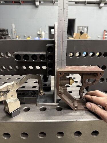
We have a bunch of these to make and wondering if your fixture table would be able to do something like this?
That’s easy. This took 2 minutes to set up. This is an example.Processing: IMG_4270.jpeg…
I like this setup better it frees up the area in the corner of the fixture to weld.
it’s square too
I lost a long response from my phone but I’ll try again.
No one has asked what does it do or how does it function. These are often critical questions.
Both bit part and assembly (weldment) dimensions are on the drawing. This is a crutch for the designer and may cause gue$$work for inspection (bit parts), fabrication (welding), and final inspection.
There are no tolerances on the drawing. The dimensions seem to be “the designer’s purest intent” (how I sometimes describe GD&T Basic Dimensions) but how far off can any of the dimensions be on a bit part or assembly and have it still work?
Are the bit parts assumed to be flat? What if they aren’t (quite) flat?
I noticed Jason’s proposal didn’t include holes in the bit parts. What is more important, the locations of the holes relative to the base? or the locations of the holes relative to the edges of the parent part? Will the two 0.44 hole locations in the weldment go bad because the vertical piece is a bit too long or short? Is the 0.63 hole supposed to be on the actual centerline of the foot (however wide it actually is) or 2.0 from one edge?
I get it that with “loose” tolerances this weldment can be fixtured (thrown) together and no one will care, but these days tolerances can be tight and with no clear statement of what they actually are it is possible to wind up with a bunch of finished work that doesn’t work.
If anyone is interested I’ll say more but my audience is usually falling asleep about now…


