Check out this post:
@SHFab
This works for one piece of material, can you show the other 4 locations of the fence blocks with the correct lengths of the material. Please make a short video on your suggestion.
Sure.
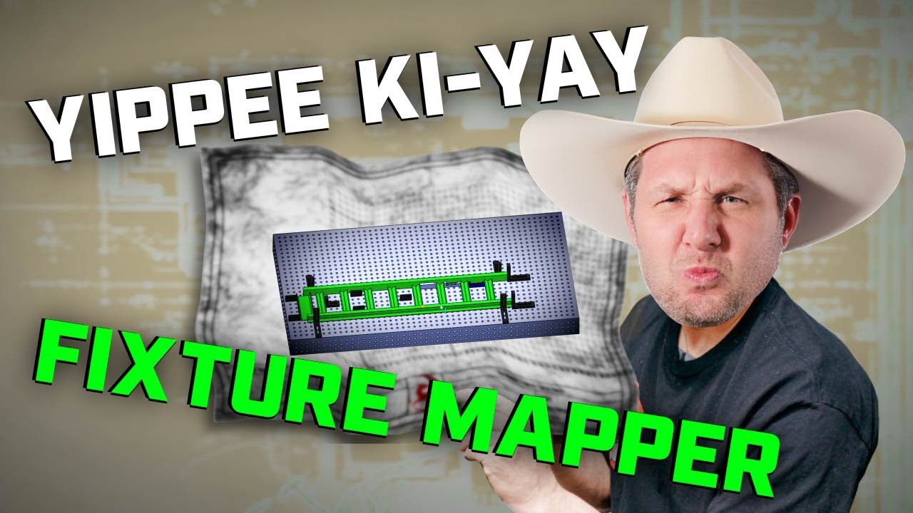
Fireball you know what would be a very nice tool a auto fixture program I sure a lot of people will see the time savings that will give you
Someday. That’s the goal
What about a video doing this in a different CAD package, for example Fusion?
Agree with the Fusion suggestion by Mlewis
Jasson
Question, I see when when you were setting up the tooth blocks, it looked like some you went from hole center to hole center and some hole center to hole edge when measuring? Or am I missing something?
Thanks for the video, nicely done!
Your recording how far the block is extended from the first hole you can get a bolt into. That distance matches the scale on the side of the block.
Thanks for the clarification!
@Fireball_Jason not sure how much you read the youtube comments so just going to drop this one in from the last video.
now that you’ve done several of these, what would be a good one is to prove the fixture map can be used by anyone, you do the map as the “expert” then hand it off to someone whos never touched it before as if they were a brand new apprentice and you just told them to go lay that job out for you to come weld later.
I’ve done this several times with my son. I have video on that. It’s very easy to understand
Thanks, I must have forgotten them or missed them ![]() might be worth giving them a shout out in the next video
might be worth giving them a shout out in the next video
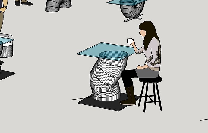
At first i thought of this as a joke. But then, there may be merrit to the egg sample.
The spec’d characteristics are going to be total height (since it’s a table); and co-planer top and bottom. Everything in between has a bunch of challenges that some of us might be familiar with, but wouldn’t necessarily be spec’d. With whatever does go on with the pie-cuts in between though, you’d have to hit the specs despite that. This would allow an example that reaches into the Z axis. And also an example of how building on a table still allows other types of holding things in place. There’d still be a need for matching and evenly spacing the pie slices. Which might for instance be done with a bunch of fine wedges between each successive layer. Basically building between a top and bottom reference fixtured in place, and free form between.
Could throw in a complication in the base plate if you wanted. Like needing to have it in place (single setup build), pretending that you couldn’t just add it to the spiral pie-cut tube once that was built.
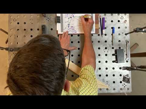
Well, thanks to all of the great videos, I decided to try and fixture a part. It really is a simple part, two 4x4 pieces with 10° angles on each at the joint and the end piece cut at 20° to get back to perpendicular.
Big issue was I don’t know Solidworks, but with the veteran discount, I loaded it up. It took me way too long to move stuff around and get things exactly where I wanted, but the mate command is nice. I never could get the center points of the holes to show up and since I’d about had it with the program, I decided that I could measure off the hole edges. That is equivalent and it ended up working.
I also haven’t received my 1/16" washers yet, so I set the blocks 1/4" (4/16") and 1 3/8" (1 6/16") and then used 1/16" shims to get the blocks extended correctly.
Owing to the fact that I have a 54" x 54" table, I had to support the far end that was off the table and then flip the part to repeat. I needed two of the parts, so had to use the fixture four times. Man, it was nice having it set up.
Thanks again Fireball crew!
I left a comment on youtube.
@Fireball_Jason Here is the video. I hope it’s ok.
Love the 5” Adjustable Fence Blocks.


