What i THINK i've learned while planning my fixture plate

This mostly talks about hole pattern in a fixturing surface. Philosophy of design approach.

For sure, there can be one variation of a tool that’s ‘best’ for scenario 1 and another for scenario 2. But i think the scheme i’ve come to is generalized enough to be useful discussion on a hole pattern to choose if you have ultimate freedom such as making a fixturing surface yourself.
, , , This stems from my planning and playing with what i want to do with a 1" thick plate i bought. Surfaced; 686 mm X 408 mm (27 x 16 inches). Since i can’t have a table, this plate could be a half step. Part of me want to just cut it in half and have two (62 lb) strips, which might act as squares sometimes, and might join back together if needed to be the table approximation.


But i think i’m decided on keeping it one continuous piece (surface) since it’s machined flat and i don’t want to ‘break’ that.
, , , So, where do i drill the holes?
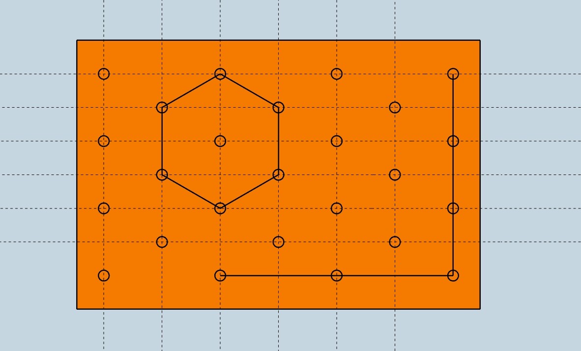
Looking to commercial examples, there seem to be two main versions of a cartesian (X-Y) grid. With either all rows and colums in line, or every second alternating by a half step.


A purely linear grid has some advantages. But i’m the kind of stubborn that i have to work through every choice myself. And when i set to exploring the characteristics (thus pros and cons) of the ‘offset-by-half’ alternating rows pattern, there’s the characteristic that not all holes are equally distant apart. As you can see above. Usable, but is there another way? I explored “what if all holes were equi-distant?”
, , , Hexagons are equidistant between all neighbouring holes.

And i got majorly side-tracked thinking that hexagonal hole pattern layout was the most advantageous.

See, a rectilinear grid is great … for rectilinear things. But if i’m allowed to say that “we often enough deal with other shapes” that maybe our hole pattern should deal with them easily too. A hexagon lets a round thing be located by three points that fall naturally the same distance from it’s perimeter. Etc. And an array of hexagons keeps sets of holes in linear alignment (there are still lines of holes at 90 degrees), though further apart than in a simple X-Y grid. So it actually includes both worlds (rectilinear, and beyond), so you could do things like locate a cylinder in reference to a length of square tube.
, , , However. Hexagons are just a special case of an array of triangles.

Which got me thinking whether including one more hole per hexagon, and making an array of triangles, was even better.

And what do you know, it is all of the same goodness, just better. But it’s not only a derivative of the hexagon pattern. Look again and it’s a version of the alternating-offset rectilinear pattern too. A version where all holes are equidistant. If you like, a version where the spacing of columns is determined by the hexagon, as opposed to determined by a square grid.

, , , This has additional outcomes such as being able to automatically reference 30 and 60 degrees (in addition to 90). Using the same tooling (eg stop blocks) at each of these angles. And being able to use triangle math in setting up fixturing (so, easily build triangles for one thing).
, , , There are two important characteristics of the equilateral triangle pattern. Which perhaps might be considered ‘lost’ from a pure square grid. Or perhaps ‘sacrificed for’, or in trade for, the other things like accommodating circles.
, , , One is that the distance between columns is not the same as the distance between rows. In one axis you’re dealing with increments of one size, and in the other axis another size. This could be accommodated for in the tooling used with such a pattern. (eg: pins with various size heads to take up the difference). But probably doesn’t need to be, and doesn’t have to be viewed negatively. To me it means i can work on a weldment that needs closer hole spacing by standing at one side of the fixturing plate, and work on a weldment needing greater hole spacing from the other side. More variation more better kind of thing.
, , , The other ‘consequence’ (of having lines of holes at 30 degrees, 60 degrees, and 90 degrees to each other) is that there aren’t any at 45 degees. This is a biggie. I haven’t sat down and explored whether tooling can re-incorporate this function. But perhaps there’s an aspect of ‘approach’ (fixturing method) that incorporates it anyway. If i’m going to be working with a 45 degree reference tool (a 45 degree ‘square’) in my arsenal anyway, then i do still have 45 degree capacity. I’m just not using the fixture plate itself for this in my fixturing approach.
, , , I then played with which orientation i would want the pattern on a rectangular fixturing surface.

In one ‘direction’ in the pattern, rows of holes are closer together than if the pattern (or the rectangular plate) is rotated 90 degrees. To me, one is superior. In one i can have the same number of rows and columns in my (4:6 ratio rectangle) fixturing plate. And have whatever loss of ridgidity happens due to holes be less pronounced in the longer axis of the plate (more space between holes in that direction), so that bending of my plate will be more even between length and breadth than otherwise.
, , , So my take-away from my re-designing the wheel (hole spacing pattern) here is that there’s a trade-off between a square offset hole pattern - with equal column and row distance and automatic 45 degree rows, and an equilateral triangle pattern - with 30, 60, 90 capacity; circle, hexagon, etc matching; and greater variability.
, , , But what am i missing? Is there some reason that straight up rectilinear pattern ( no offset) is better than the alternating offset pattern? And my triangulated version is moot? Is there another option still? Maybe golden ratio offsets? Did i miss some easy addition to the hexagons pattern that makes all dreams come true?
, , , I think i’m going to drill a grid pattern with equidistant holes. (On 100 mm centre to centre - to lessen the drilling) And force myself to develop tooling for this pattern, and learn how this tooling ACTUALLY has to be to deal with both circles and squares, etc.

Holes on a fixture table system serve two purposes. A good design takes these ideas into consideration. The first and most important function of the hole is to create a scale, a unit of measurement that is more accurate than a tape measure. To make this function more useful a straight grid pattern is easier to use, much like a piece of graph paper is easy to draw or sketch on.

The distance between the holes or resolution is very Important. Things that can affect the hole spaces are the supports under the table surface. It’s not a good practice to have a blind hole over a crossmember or ribbing. If the holes are spaced far apart like 4in or 100mm this is great for the manufacture because it reduces the number of holes. The trade off is the fixtures need to be larger to span the larger gap between holes.

The hole size plays a role in all this. Large hole sizes like the 28mm tables often have the 5 hole pattern. This is 2 grids on the same table top. To me this is just a marketing trick. It’s a way to make the table seem more useful than it really is. The holes are still spaced 4in or 100mm apart. The tooling is large and expensive. The only advantage is extra holes to place clamps. The tooling needs to grab 2 holes at the same time. For example a 4in hole spacing requires a 8in long slot or adjustment. A 2in center fixture only needs to have a 4in slot to grab 2 holes.

The fixtures play a big role in the hole spacing and locations. For example: Can the pattern be duplicated on the fixture? Can a fixture to fixture be bolted? Can the hole pattern be expanded to another surface or down a skirt of a table? Does the hole pattern work with other fixtures? Lots of conditions need to be thought out before a hole pattern can be chosen.

1 Like

You’ve obviously chosen wisely the characteristics of your table system. Everything you say shows consideration for why it should be that way. I’ve watched the vids running through ‘the why’ on the choices made. I really appreciate those descriptions. And thanks for running through it again here.

I agree, the “two grids on one table” isn’t true, so that description is just a marketing expression. It’s all the same grid, just choosing to offset some holes’ positions. And since when you do that you have to re-consider spacing, there’s little in the difference between purely linear and alternating-offset linear patterns. Unless that is, the alternating offset spacing is determined by triangles as my suggestion / option / possibility described. A triangle grid has some fundamental differences beyond whatever the marketers would spin it as. If the one is called the “5 hole pattern”, would mine be called the “6 hole pattern”?
, , , But are those differences worth the trade-offs. I haven’t yet decided. Everything’s a trade-off.
When it comes to hole spacing particularly, there’s something i’ve wondered. Do you know how you chose 3/4 hole size because as an intermediate it’s actually better (best of both worlds). Well, there’s something between 2" hole / grid spacing and 4" spacing. If reality were splitting into two worlds tonight - one where there existed a tooling system for 3" grid spacing, and one like our current world where 2" and 4" are the options, i’d choose the 3" world and drill my plate to 3" spacing. I drew it up as an option. But am starting with 100 mm spacing in my actual plate because i can drill more later to convert it to 50 mm by adding holes exactly mid-way. When i can afford all that drilling.
, , , But that also may never happen because… this plate that all my contemplation is over is a stepping stone. A lot more like a table with holes in it than a precise reference tool. Exactly because, as you say, the first function of a proper table is to be an accurate scale, and i’m not going to achieve that with DIY drilled holes. So this plate is what i will use to make the money to buy the proper thing.
, , , So my considerations for ‘where to drill the holes’ are a lot different from a tool producer supplying a whole system of interdependent parts. But i do like to let my imagination run on the hypothetical (?philosophical) best design (that couldn’t be commercially supplied since we’re locked into tooling sets; trade-offs of manufacturing cost; etc… ) And since a triangular grid / hole pattern looks like it should be possible in terms of considerations of crossmembers; fixtures that work with it (duplicating hole pattern in the fixtures); etc, i like it as a possibility for that hypothetical ideal. Though everything is a trade-off. It may just be two slightly different alternates best for different applications. It’s a pity we’d need to build out an entire system to check by comparing usefulness to the fabricator. Maybe my one little plate can be a test bed / prototype in a way if i do drill it ‘triangularly’.

Don’t forget you may get to reinvent the wheel when it comes to your fixtures if you don’t choose a hole size and spacing that matches the standard that at least one company uses. Do you want to make parts to make parts, or make parts to make money? No wrong answer, just make sure you really know what you’re getting yourself into if you go the route of not following anyones standard.

1 Like

got to say, I’m crossing that thresh hold in life where I don’t have to make everything just because I can, ( or think I can :rofl:) . no Disrespect do what’s fun and rewarding to you! but I’ld rather be making stuff for people than myself anymore!

1 Like

Thanks. That’s a great point.
In my particular case, i’d probably be making my own tooling (for this plate / experiment). Then buying into an existing system when the homemade plate and tooling has facilitated the earnings to do so.

I get it for sure. That’s the wisest approach. I’d jump that threshold myself if i could. I’m still backing up for the runup though. Have to make-do with what i can find at scrap yards, and build myself. And thought i’d ‘show my workings’ of what i found along the way.

Just buy one of the heavier version tables from Jason. I’m all for making your own but I didn’t even think twice about getting one. Sometimes the juice isn’t worth the squeeze DIY ing it.

2 Likes

Any word on availability of the 3/4 drill template!?

My last job, my table had the circular pattern. It was useless for 100% of the projects i did. Including cirular projects. The diameter of the hole pattern was never close to the project.
Granted, the company only provided dogs and bolts as fixture tools. That was for food/pharma stainless one offs, prototypes and small production runs. You know, all the things you need good fixture tables and good fixture tools for. I paid for and used my own tools. That table was useless. That pattern was useles. I wished i could have been provided with a traditional 2" center to center grid pattern.
You’re over-thinking things, trying to make a ‘perfect’ table. You wanna know what I have? A 2x3 fixture table I bought, and a work table I made from an old project. It was a trebuchet. Since I got tired of waiting for the apacolypse, I turned the supports into legs, bought a piece of scrap 3/8" and that’s the one I use as a mobile work bench. I can abuse the crap out of that one so my fixture table will last decades.
Buy a fixture table. Use your sheet to make a work table you can beat on. Or, buy a pattern maker, rent a mag drill and spend a weekend drilling holes. Honestly, the man hours you spend drilling isn’t worth it. I get it, you like analyizing and want a perfect tool. You research, run models, etc. Dont go down the rabbit hole. This is coming from a guy that focuses on the tree bark instead of the tree or the forest too often.
Unless you’re getting paid to reinvent this wheel. Focus your energy on making fun things, or things for the apacolypse.

1 Like

Thank you. Good to hear perspective from another barkologist.
, , , I’m not necessarily trying to invent the perfect mouse trap. Perfect can only be perfect for a particular scenario or use case. And since i’m talking about a ‘general purpose’ fixture plate, you’re right, ‘perfect’ is impossible. But better? A better mouse trap? Many have wasted a chunk of their life chasing that pipe dream. A chunk disproportionate to the return. So once again, you’re right, it would be a safer bet to make a living playing with commercial tools than re-inventing the wheel. But that is a bet. And with a bet there’s always another side to it. Maybe some bets suit some people better like some fixturing setups suit some fabricators better? I guess i’m betting that my all too common practice of chasing rabbits down holes pays in some way or another. Maybe like the kid who takes everything apart and therefore never has functional toys to play with, but learns how things work. And like that kid, this analytical, philosophical, exploration is my fun. And whatever fixture plate i come out with will be better than the nothing i will have any other way. Which will leave me in better stead in the apocalypse.
, , , I can’t buy a fixture table. I’m working on it. In the meantime this plate is going to be something that helps me get to where i can. Or maybe becomes a prototype that gets me supplying fixture setups in my country? Who knows. So yeah, i’m absolutely overthinking this. That’s the intent. Not the right intent for most.

1 Like

The rabbit hole worked out for Mr. Jason at Fireball. If the rabbit hole keeps you happy; I’ve been there, too. I hope you keep tweaking your design and come up with something inspiring.

2 Likes