Once I start fitting things together in the next week, we’ll find out how well or horribly wrong this project goes. So far so good. Even if falls below my expectations, it has to be better than welding on make shift tables.
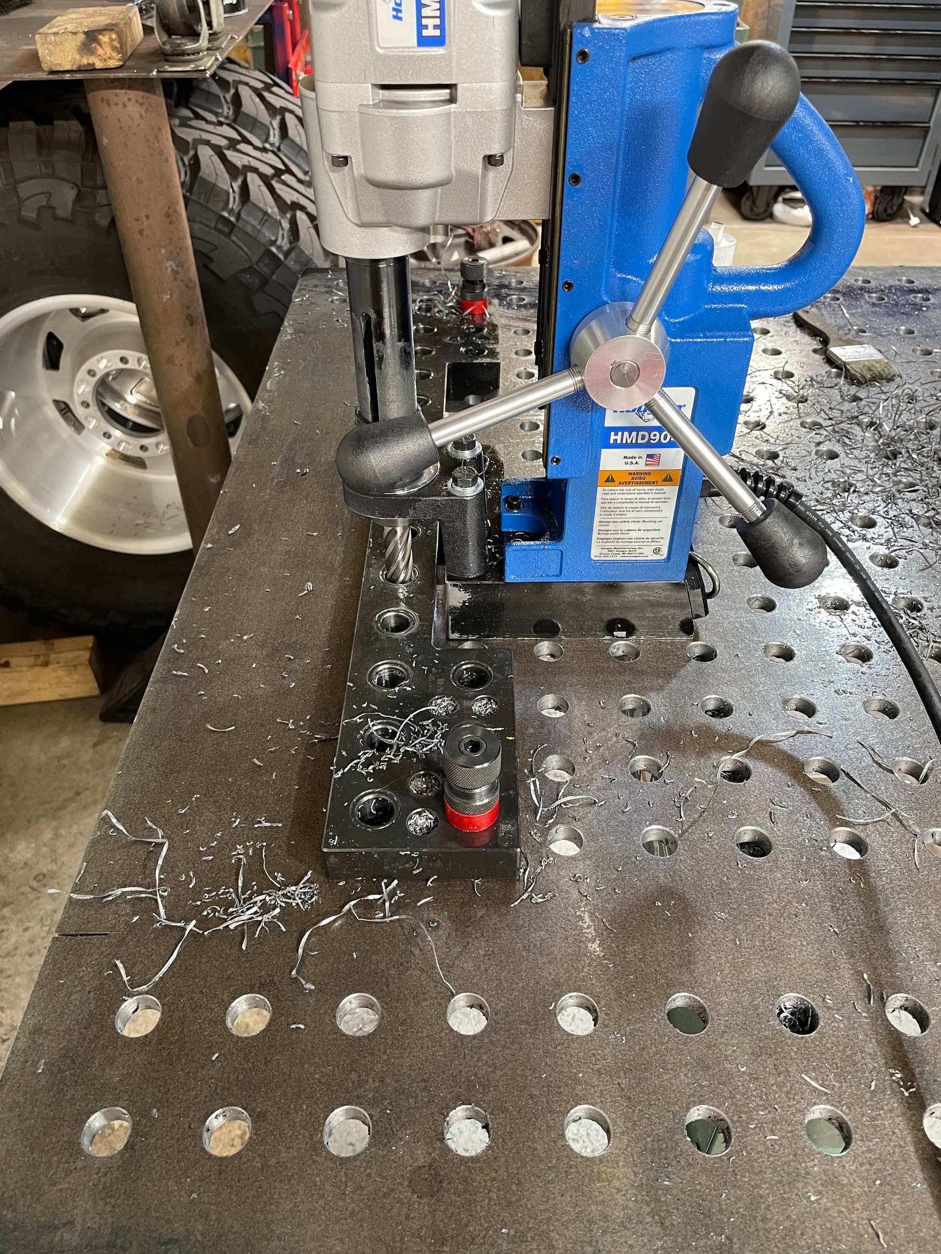
Highly inefficient but it works and haven’t killed a cutter yet. 2” DOC depth of cut arrives tomorrow. I don’t like it but in order for it to work, the drill has to be lifted every hole to clear the template. Hoping this will have a competitive edge over what I’m currently doing- drilling twice.
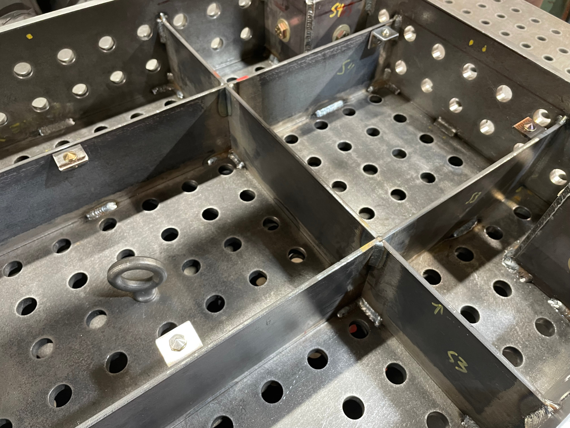
It’s a lot of work. 368 holes so far. All the skirts will be cut from the primary table surface in the next days off. Small wins are showing, I can utilize the holes drilled in the side skirts for clamping
2” depth of cut worked great today. Clearing chips wasn’t as much effort as lifting the drill a hundred times. Not much faster but less hassle drilling the holes one shot
Last picture of all these holes I’ve been drilling. Started sept 11 and finished today.
This is the 30x60 table with 6” skirts. I believe all 578 holes on this table were accomplished with the same S&F HSS cutter. 1.5 gallons of coolant was harmed in the making of these two tables. 31 lbs of material removed this time.
Unlike the video, I prefer to keep the template on the same axis to locate the next row and reverse the location of the drill. Utilize the reliefs to jump across and make inboard guide holes and reverse the template for production drilling. Repeat this process for the last 3 rows.
Or if you’re constructing a table in the same manner I am, you can utilize the side skirts if they weren’t already chopped off. This allows a full row between tacking bolts for production.
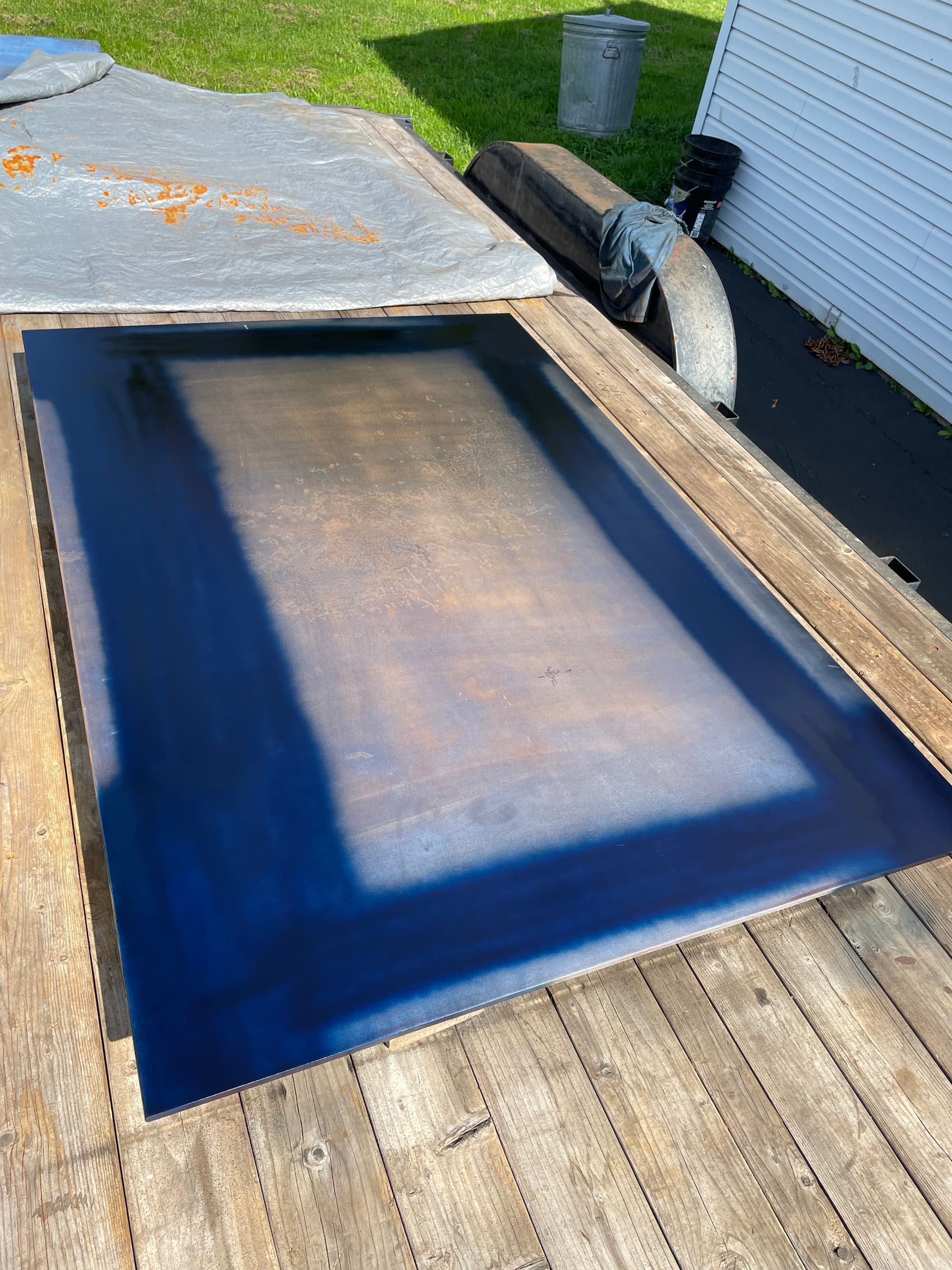
I just created created a fixture plate for a welding cart. I did the work outside and I suspect there a thermal coefficient difference b/t the drilling guide and the A36 1/4” plate. Close holes accepted the pins but far holes needed some convincing.
You’re saying that you used the fireball template but have a discrepancy in different axis or the far end of the table? I noticed that my template does not line up when laid across the length of the table. So 90* to the orientation of how they were drilled. The fence blocks will fit in either axis across 2” but not the template across 28”. There must be a slight error in my template.
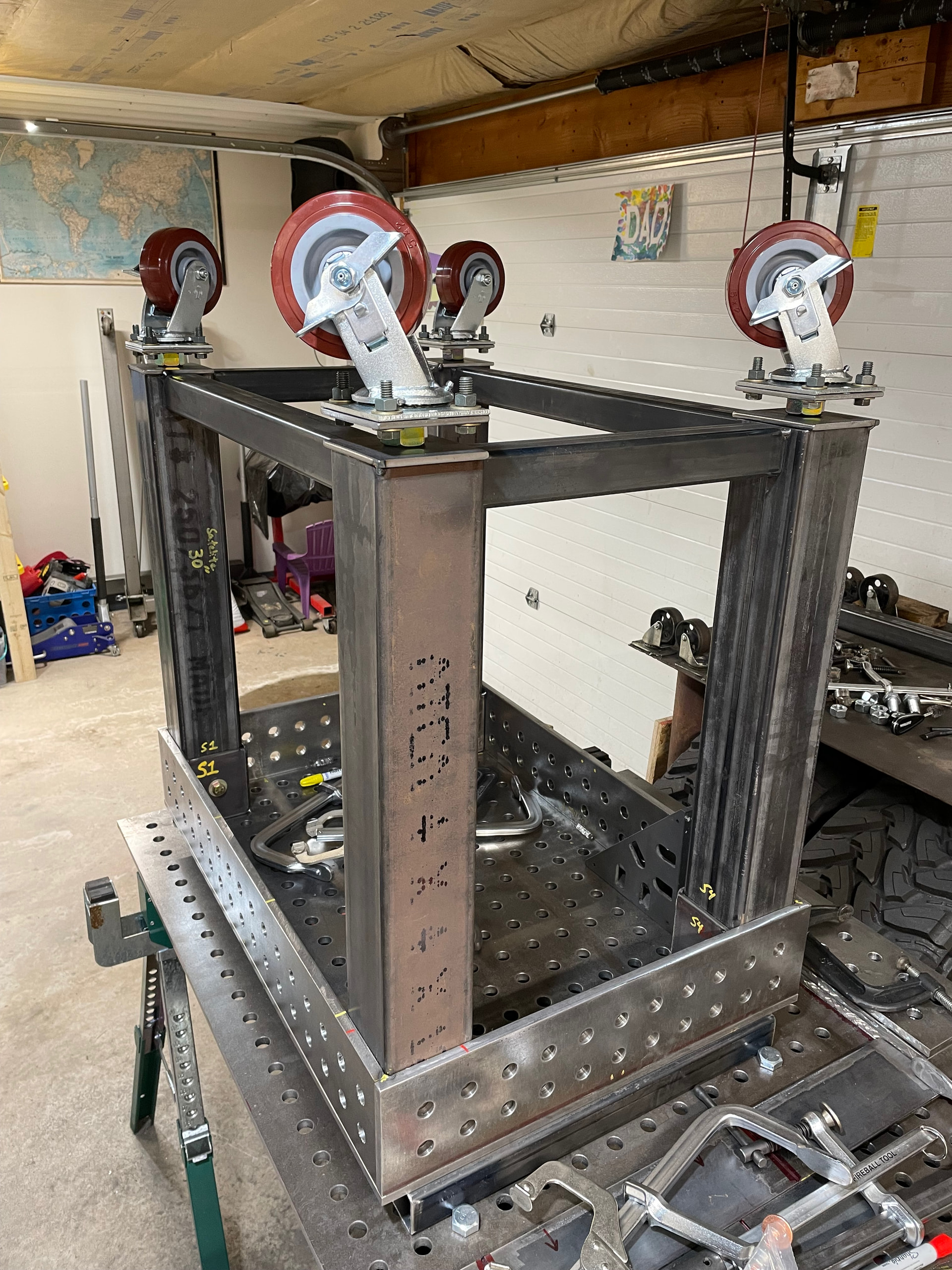
And a cool progress shot. How the table and fixtures can aid in their own construction. I’m impatient and tired coming off a night shift and not sure how much I want to dial in the accuracy of the weld joints. I figured two wrongs must make a right so I bolted the satellite table to the primary to pull everything flat and began utilizing the tool system
Still chipping away. Small table hasn’t progressed much because I’ve been tooling up for a production run on the table legs. This week will be a bunch of visual progress.
Been building a specialized tool for setting 1/2” rivnuts. Pictures of that in another post.
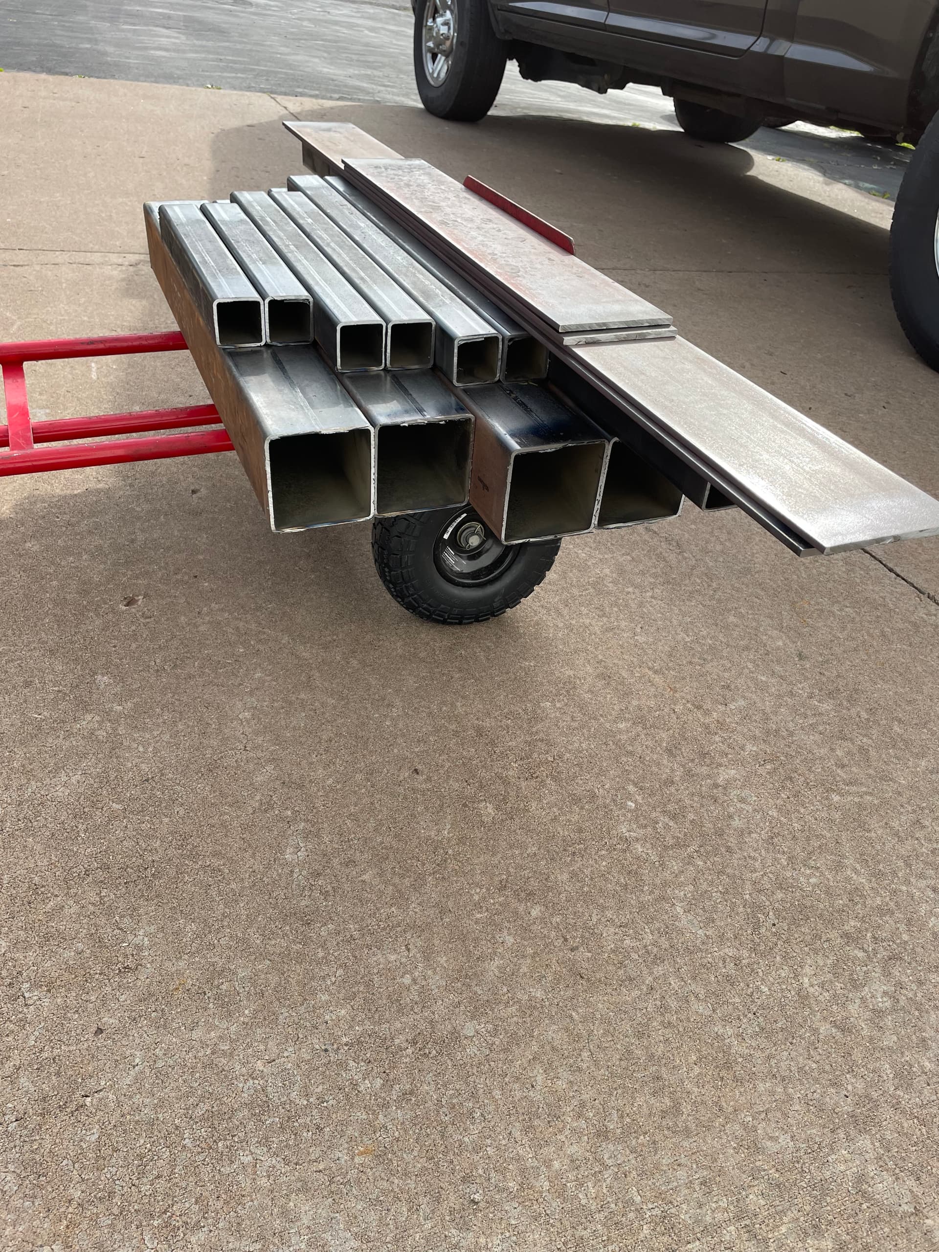
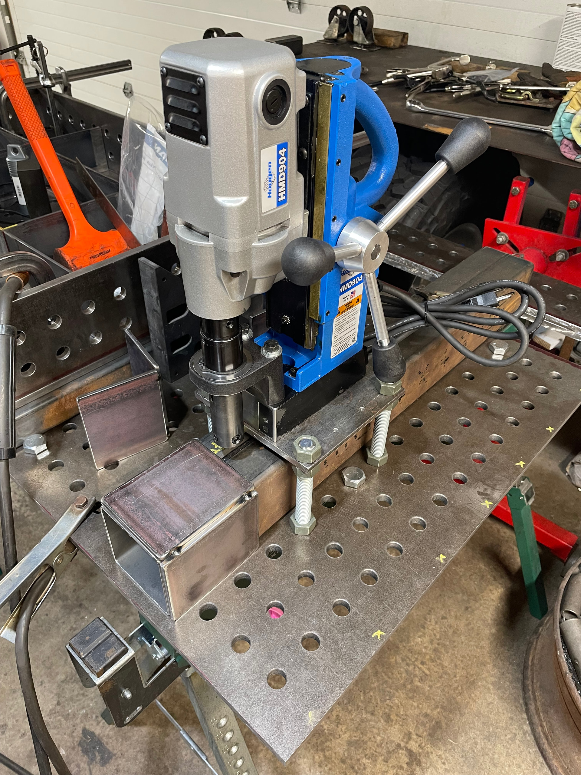
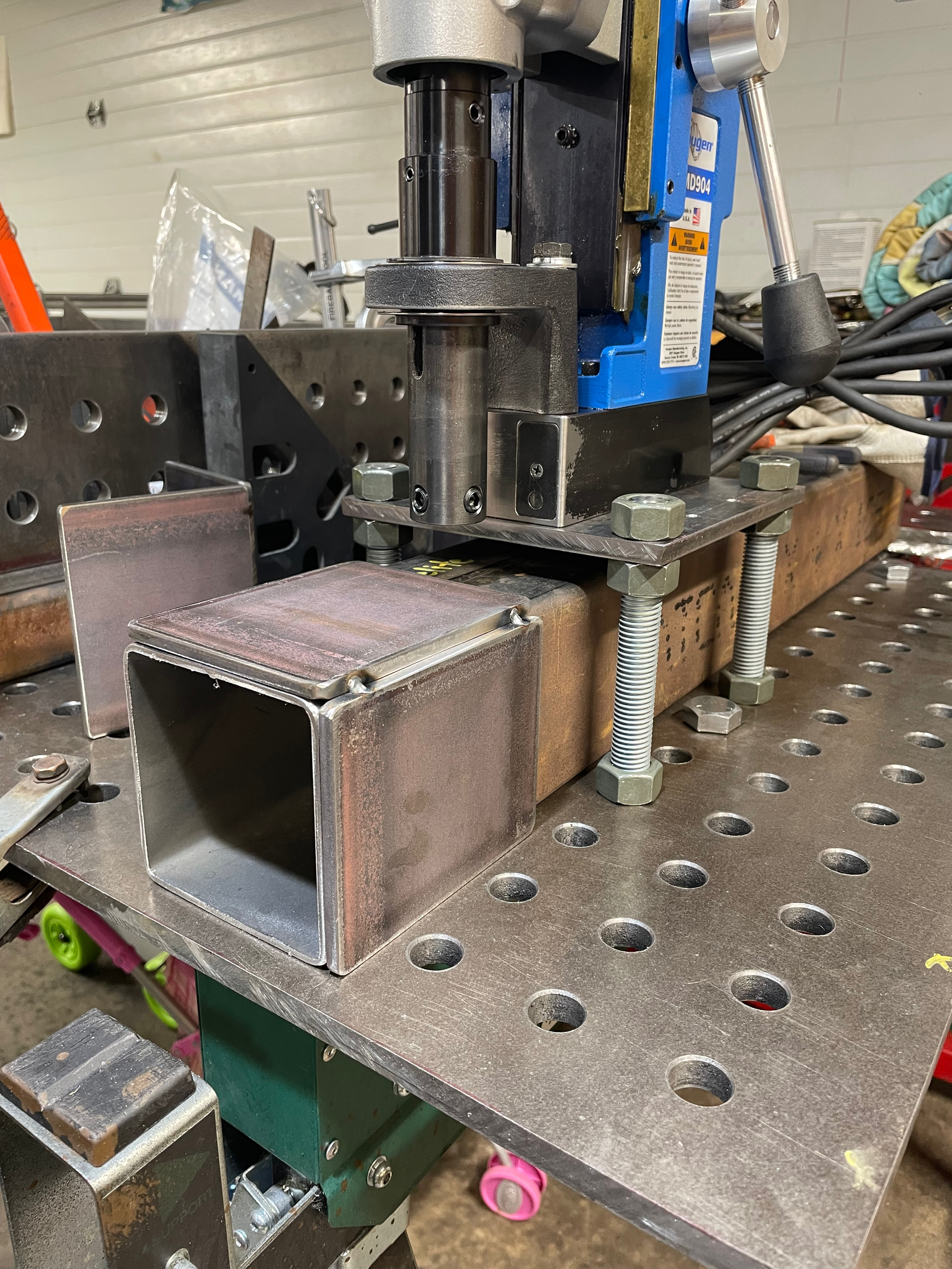
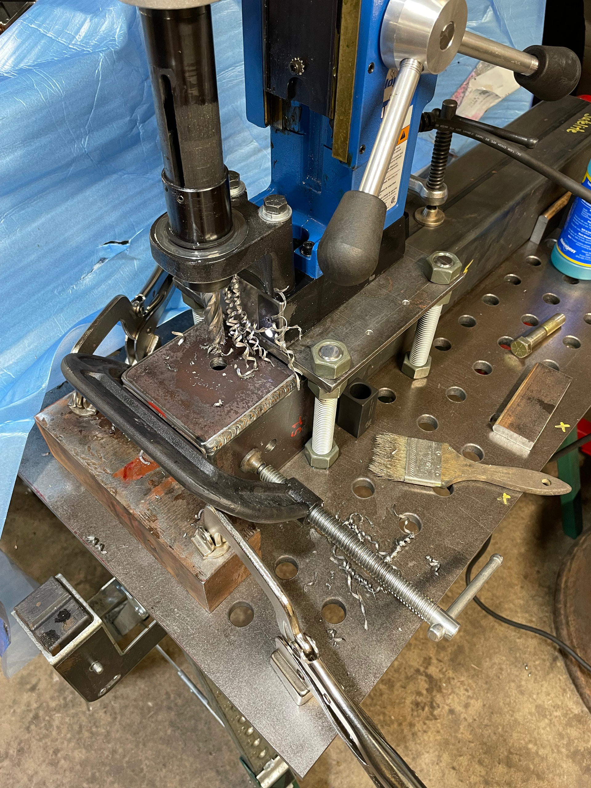
Built a jump over table for the mag drill. This will allow a one time setup and production for 16 leg mounting holes. Plate can be used for lifting in the future.
Tomorrow I’ll drill the 9/16” holes. Then I can fit up the table legs and continue welding out the fixture table. Pictures of that and the final fixture pictures for the legs to come.
Can’t wait to flip the first table over!!! Still anticipate a couple more weeks. It will be tedious prepping the threaded/leveling casters etc.
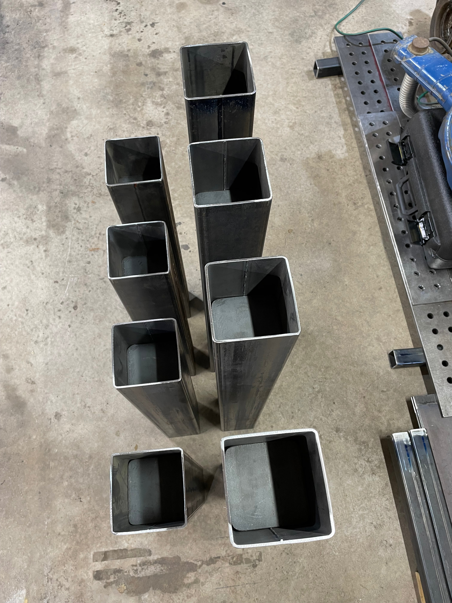
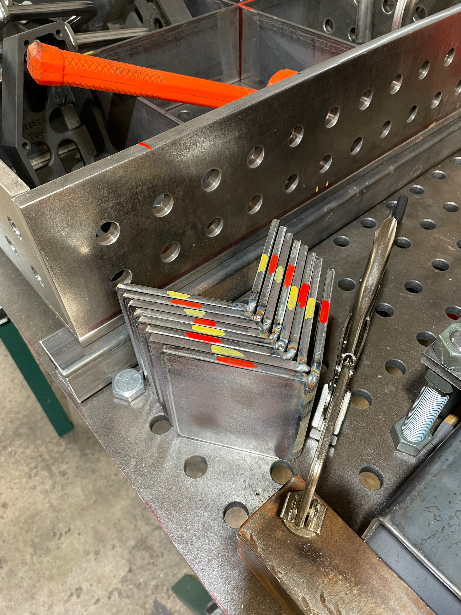
Leg and mounting socket progress. Each leg required a 4 step operation but didn’t take me too long. Drill leg, slide socket box in place, drill, rotate, repeat.
Ahh forget it, maybe I’ll remember to select them in reverse order next time. Picked up some double goose neck clamps, more 4” blocks, 6” blocks for the 45* grid feature and a couple of tooth block setups.
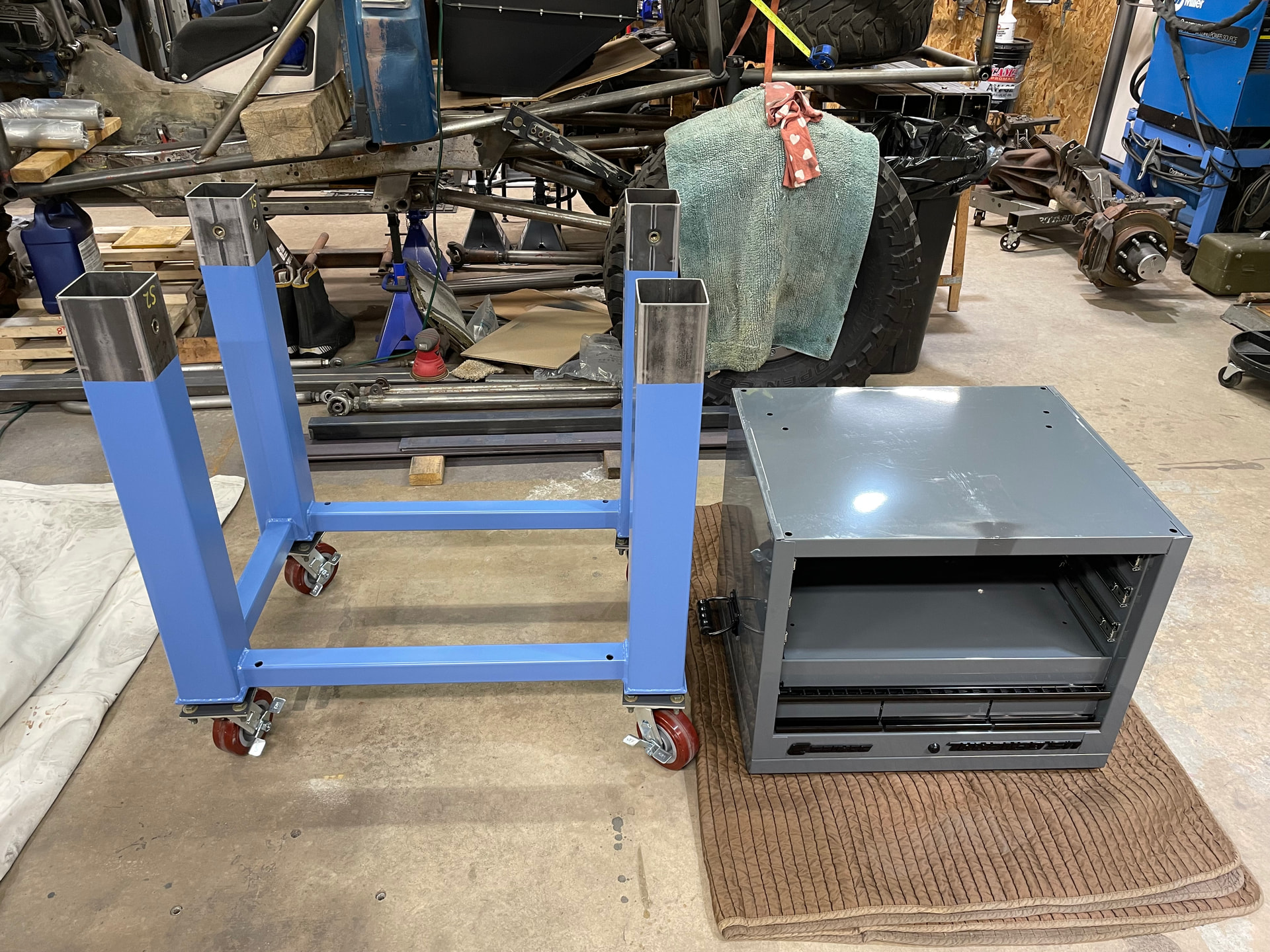
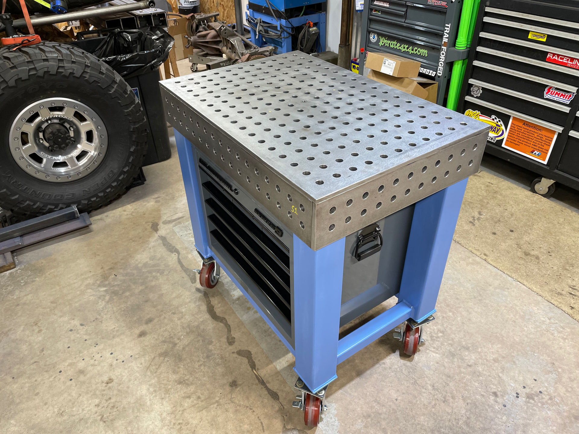
That was a great idea; getting a store bought toolbox instead of wasting a ton of time fabricating something for storage underneath. Gonna have to remember that when I start on my table; I’ve only had the parts for about a year
I had made a chip tray. During the late phase of the build it was gonna be a close call or decision whether or not it could be used because of the unplanned toolbox. The tray could be used had I elected to remove the toolbox lid but I didn’t like the look of it. Cosmetically the box looks better with an unusable locked lid. That’s a decision I’m comfortable making.
I’ll attempt to make the tray 2 piece and should be able to install it. Potentially small parts could fall through the surface but they would be captured and compartmentalized in the 4” webbing. A magnet or pincher finger tool could retrieve easily.