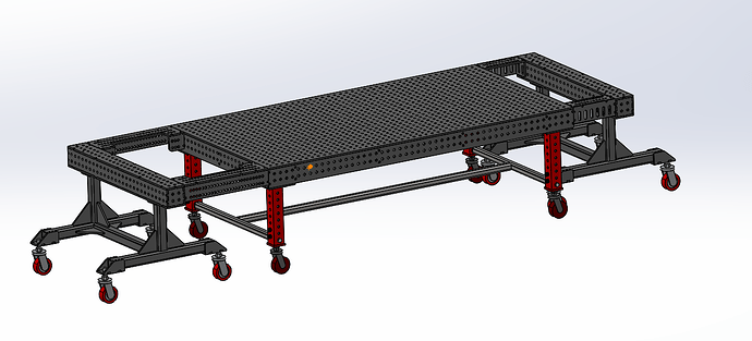
Fabrication is incredibly simplified by having a big flat plane that we call a fixture table, to reference; rely on for ridgidity; build tooling onto. But we know that a whole table isn’t always necessary; that some shops do tasks which favor re-configurability; and that some builds need fixturing that isn’t one big flat plane.
So could we get both from one set of core fixturing pieces? Both a table when that’s needed, and smaller, separate, reference and ridgid backbone to build off of. Obviously something has to give. That’s probably going to be precision. But maybe the trade-off results in a more useful tooling set?
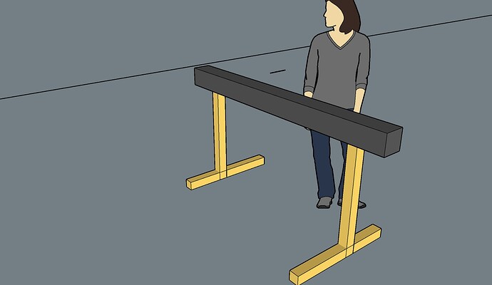
… It started when i realised that the ‘trestle’ style beams have a lot going for them in my particular scenario. I’m not aero-space, and i don’t have room or cash for a dream fixture table.
Two of these can create a (variably sized) horizontal plane to work off. One of them is enough surface area for tiny welding tasks. They’re available with hole pattern and machined accurately. Etc.
But could i have most of these characteristics in a beam that i make myself? (availability in the 3rd world sucks)
Well, it’s a beam, fundamentally. So what ‘beam’ inspiration could we look to?
We know of I-beams and H-beams. And many fixture tables, similarly, get strength and dependability by creating depth with webbing. Though most tables have only the webbing and not the lower plate layer like an H-beam does.
So is there a solution for webbing in a beam when the beam is to be a fixturing reference beam?
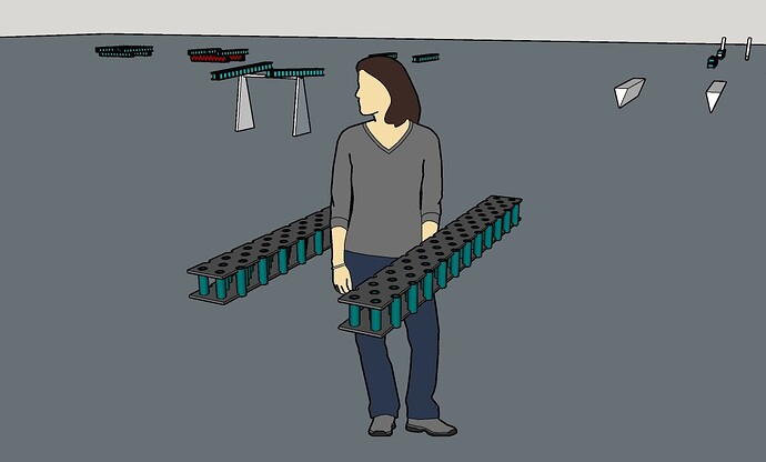
… In the design world, what you’re always trying to do is combine aspects / physical parts. And a fixturing beam has those aspects of structural dependability, (by depth / webbing), and also the aspects of holes. So what if we do the webbing by connecting the upper and lower plates at or between the holes? The holes need more ‘meat’ surrounding them (than the 8mm plate i want to use can provide) anyway, so add add material there, but just continue it between upper and lower holes. Creating the structure (webbing) of a beam. And now two aspects are accounted for. We have structure, and tube fixturing holes.
Do-able / the doing? Investment into making beams.
If i’m thinking of building a fixturing platform myself, i have to consider the ‘how’ of that happening. And how long that how is going to take me to do. So i don’t want days of dirlling holes inaccurately. But one thing i can lean into is welding. So get some plates CNC cut (including holes positions), and weld in the sections of a commercial product pipe. (there apparently exists seamless pipe with 3/4" ID and 5.56 mm wall thickness. For a total of ~ 30 mm OD. Shedule 160?)
… The beams can be used individually. Or a few spaced apart. Uup on something like uber saw-horse legs / stands. And i remember a video on some epic saw horse / trestle legs.
Or, combined to create a larger surface (table top) when they’re directly abutted (joined) together.
But you’re not just going to abut beams and get a dead-flat continuous table top out of it. I mean there’s error introduced whenever you’re joining parts. So how to do the joining of the beams for a ridgid, reliable, and accurate-as-possible table? Even roughly in the ballpark?
… I’m sure some connecting members could be bolted between (accross) the beams. Either on the underside, or, because of the nature of the space between the webbing tubes, on the ‘inside’ of the beams.
… But i feel there’s a better way.
If we found a novel solution (for the form of the beam) by combining functional aspects above, then can we do similar to solve the joining challenge? Are there characteristics of the beams that we can exploit for the function of adjoining them into one big slab?
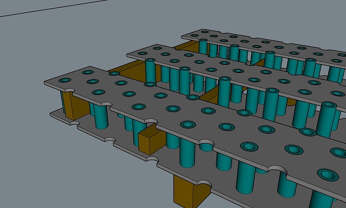
I’ll spare you the iterations of beam dimensions and hole pattern that led to having the ‘half hole’ cut-outs along the edges of the beam’s plates. But what might seem to be a terrible characteristic of having some holes centered at the joining of two beams and on the edges of the beams, leads to the half-holes being positional references (like a v-block) and locator sockets. Let these precision cut features locate around further tubes acting as pins, and you’ve got relative positioning locked down.
… Make these pin tubes a little different than the ones built into the beams, by giving them shoulders that jams them in between the plates of the beam, and you’re now referencing adjacent beams in the Z axis also.
So we have beams that are highly useful individually, that now in addition can come together accurately and become a table top.
Interlinking, but that’s not all that’s necessary is it?
Well, i say “locked together”. But the one big thing that’s missing is a means of KEEPING the beams together in their referenced positions. Hypothetically a ratchet strap would do that. And Jason’s shown us what a ratchet strap is capable of. But in a fixture table scenario, where push and pull forced on the table top might be forcing the beams away from one another, the give / elasticity of a strap probably isn’t a reliable solution.
…And i don’t know what the solution should be. I’m thinking some sort of bolting together apparatus that joins each beam to it’s neighbour. (vs one long bolt accross all beams in the slab). But i haven’t designed this yet.
Fabrication
A cut-away view shows how chamfeer-ing gives place for weld. Weld in the gap. And consequently how the assembly can be welded from the outside.
The welds will have to be addressed (ground flat).
I’m thinking that the tube-pins used for interlinking the beams could also be tooling during the build of the beams. If clamping against them in position aligns the parts (the plates) well enough, and strongly enough, then this could be the means of positioning the parts for tacking together.
A judicious and plentiful set of tacks, followed by strategic weld order while welding the tubes into the holes in the plates, should leave the parts in their relative positions. That much structure (number of tubes) all tacked in, should hold against any movement that one full tube end weld at a time will try to effect.
…
So WHY have the option of separate fixturing beams, or smaller sets?
Transportability - The beams i’ve drawn and planned for my build will be approx. 48 kg each. I can move that in ways that i couldn’t move a fixture table or wagon.
Small start (to grow with) - Needing only one or two beams initially; adding more to be able to form a big table; adding more as extra tooling.
Multiplicity - Imagine a job of small assemblies. I can give one or two beams to each of 3 fabricators and have simultaneous production happening. Perhaps a station for each stage down the production line. And then back to being a slab table on Tuesday.
Variable size / form - adaptability to the weldment’s scale and shape. A slab table when you need it. A tetris layout of beams accross as much floor space as is needed for the project of the moment when you need that.
Out of plane - Table parts used in layers. As tooling themselves.
Expansion AND futureproofing - Especially if you were going with home-made beams, You could always make some more. Whether this is upon busines growth, or unlinked to a supplier possibly going out of business; selling to off-shore interests and dropping quality, etc.
Purposeful misalignment - One big solid plane is nice. But there are things that are very difficult to ask a monolith table to do.
Unexpected usefulness - The form of one of the beams can come in handy in unusual ways. And the set therefore has more general purpose functions than a slab table.
Like the v-block effect allowing large pipe to nest in position.
Or just somewhere to manually spin smaller round parts while grinding the end edges, without them rolling away.
Adding accessory tooling - like rollers, turning the beam into a materials slide.
Two lips - The side of a beam, whether individually or as the side of a table, isn’t another full surface / face as in 5 sided tables. That’s usually a trade-off with having a lip at the table perimeter to clamp to. But having two edges (of the upper and lower plate of the beam) gives two reference points which should together be square to the top surface. So it’s kinda the best of both worlds.
Alternately, having individual portions that can be variously arranged means that there is another way to get hole baring surface facing both upward and outward.
Assistant to the manager - Beams as accessory tooling.
One level fewer tooling - A beam can be more easily held at an angle; or spun between rotisiary stands; etc… Now, instead of additional fixturing upon a table to hold parts in this position, the beam is both the table and tooling.
? Beyond Fixturing? - A shop doesn’t only need fixturing. Maybe having beams that can be more generally useful is worth something.
They can be stacked as blocking.
Or arranged to form cascading support for stair parts, or for numerous small 90 degree bracket parts to be clamped to all at once, to be welded out all in succession (less machine idle time).
…
I went lengthways
I’m planning to make my beams ‘long’. The length of a table rather than the width. They’re more useful this way. More likely for one to span a frame weldment. More positions to attach a hoist to on either end when i use the beam as a pallet to raise my fly press onto it’s stand. Fewer joints for less inclusion of error. Etc.
But beams could conceivably come together into a table format like the plates of Build-Pro style tables.
I guess the point is that if i’m making beams of this kind myself, they could be whatever length, number, etc, that suits my case.
Mine will be 1500 mm long, and 150 mm wide, and 100 mm deep. Mostly because that comes out of standard materials in integers.
…
Designing fabrication as a system (philosophy of approaching fixturing) wrt tables / beams.
Overall then, with this system as a possibility, the single slab large fixturing table fits into the world of tooling as a special case. For any time that uber accuracy over large area is necessary; in shops where space isn’t an issue and a big table can be in position permanently; etc. Because having beams that can do a lot of what that table can do, and a lot it can’t, is probably the more broadly appropriate or generally useful fixturing set for a fabrication shop that isn’t so specialized.
… The use of beams in this way is made possible by design of a positive interlocking mechanism. Or else they couldn’t be the reliable table format when joined together. This in turn is made possible by hole pattern and interlinking parts. There might even be a better way.
… Having a means of producing of beams without much special machinery or tooling (outsourcing cutting of precision parts and then assembly in a workshop that does assembly) makes the system of beams achievable for most fabricators. Both in terms of accuracy, and investment in producing the beams in-house. And this makes ‘beams as a first order of fixturing’ attainable in addition to being philosophically a better first approach.
Supplimentary thoughtagizationizing
Bolting into long tube holes.
I know that we’re most used to ball detent locking bolts, and pins on the ends of clamp stems, which need a certain table top thickness to grip in the holes. However, there are options that don’t. I’m not describing them here, out of respect for the ball of fire that provides this forum and doesn’t sell this style tooling. But it’s very possible to lock into long holes.
Commercial Vergins
Beams like this don’t necessarily have to be fabricated (weldments). They could be made just like the table tops we know. And with all the accuracy that the system i’ve described for interlinking really needs. Beams are a better general solution than monolith tables, and buying beams would be a better solution than making them.
Degrees of accuracy
Outside of the abovementioned cast and machined version (high tolerance), the fabricated version could be machined after assembly. Will never be as accurate (movement of relieving stresses,etc.). But an intermediate iteration of the beam system, for instances where that degre of accuracy is appropriate.


